Minimum Bend radius
The minimum bend radius of optical fiber light guides is mainly determined by the tube bend radius, but is also affected by factors such as the optical fiber bundle diameter and optical fiber bundle length. Excessive bending of an optical fiber light guide can cause wavelength loss or break of the optical fiber, etc., which may result in a drop in the transmitted light intensity, leading to poor performance.
Note that optical fibers with the random arrangement specification will have a larger minimum bend radius than standard optical fiber bundles.
Repeated Bend Resistance
Repeatedly bending optical fiber light guides can cause fiber twisting, friction between fibers, and friction between fibers and the tube (the optical fiber bundle covering). This can result to optical fiber breaks or deterioration, causing a drop in the transmitted light intensity and performance.
An optical fiber light guide's ability to withstand repeated bending varies by fiber type. Multicomponent glass fibers generally have less repeated bend resistance than plastic fibers. Note that optical fibers with the random arrangement specification will have less repeated bend resistance than standard optical fiber bundles.
If you require high durability, use a bend-resistant light guide (available by special order) with a customized internal structure and special coating.
Heat Resistance
The heat resistance of bare optical fibers varies by material, with a value of 70°C for plastic, 430°C for multicomponent glass (excluding the lubricant), and over 1000°C for quartz (excluding the covering). The maximum heat resistance temperature of light guide end faces will be determined by the heat resistance of the adhesive, optical fiber protective coating and covering in use. The value is 70°C for plastic, 200°C for multicomponent glass, and 200°C for quartz. For applications requiring high end face heat resistance, use a heat-resistant light guide (multicomponent glass or quartz types heat resistant up to 300 °C are available by special order).
Quartz models heat resistant up to 500°C are available for applications requiring even higher heat resistance. The life of bare optical fibers will vary depending on the operating temperature, and the existence, degree and duration of any temperature variations present. If you intend to use the product in a nonstandard environment, inquire for details before purchase.
|
Heat Resistance Temperatures |
|||
|
Optical Fiber Type |
Heat Resistance Temperature of a Bare Fiber only (℃) |
End Face Heat Resistance Temperature of Standard Types (℃) |
End Face Heat Resistance Temperature of Heat-Resistant Types (℃) |
|
Plastic |
70 |
70 |
- |
|
Multicomponent glass |
430 (excluding lubricant) |
200 |
300 |
|
Quartz |
Over 1,000(excluding covering)
|
200 |
300,500 |
Humidity Resistance, Eater Resistance
Optical fibers do not have very good humidity or water resistance. For applications requiring humidity- or water resistance, use a special-type light guide (available by special order; multicomponent glass fiber only).
The diagram on the right shows the result of an autoclave test. (A single test cycle consisted of 20 minutes at a temperature of 132°C, humidity of 100%, and pressure of 2 kg/cm2, followed by a reduction in temperature, humidity and pressure to the ambient conditions.)
|
Material |
Multicomponent Glass |
Plastic |
Quartz |
|||
|
Fiber Diameter |
50 μm |
250μm/500μm/750μm/1000μm/2000μm |
208 μm (and several other values) |
|||
|
Core Diameter |
45 μm |
(3 to 5 µm less than fiber diameter) |
200 μm |
|||
|
Aperture Angle |
Approx. 70° |
Approx. 60° |
Approx. 25° |
|||
|
End FaceEnd Face
Heat Resistance Temperature*1 |
Standard type |
200℃ |
Standard type |
70℃ |
Standard type |
200℃ |
|
Special-order type |
300℃ |
Special-order type |
500℃ |
|||
|
Bending Resistance |
Δ |
○ |
× |
|||
|
Heat Resistance |
○ |
× |
○ |
|||
|
Transmissivity*2
(Visible light; short distance) |
Δ |
Δ |
○ |
|||
|
Price |
○ |
○ |
× |
|||
・○: Outstanding Δ: Problematic under some conditions ×: Unsuitable under some conditions
These ratings are only intended as general guidelines. Inquire for more information.
・*1: Data for bundled fibers (not bare fibers)
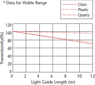
・*2: Transmissivity up to distance of 10 meters
.gif)
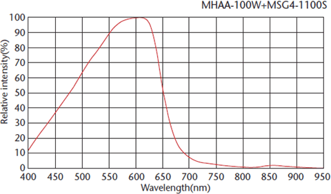
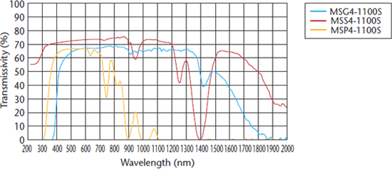
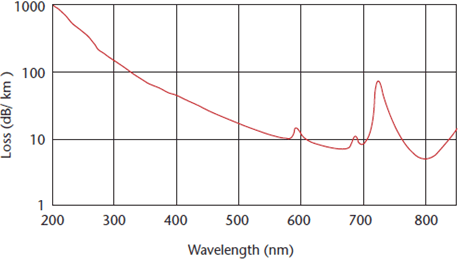
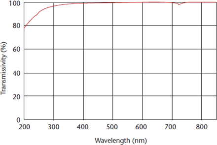
Light guide spectral transmissivity
Fiber filament specifications
|
Numerical Aperture (NA) and Structural Dimensions |
NA |
0.22 ± 0.02 |
|
|
Diameter |
Core (µm) |
200 ± 3 |
|
|
Cladding (µm) |
208 ± 3 |
||
|
Primary Covering (µm) |
240 ± 10 |
||
|
Minimum bend radius |
20 |
||
|
Material |
Core |
Pure SiO2 |
|
|
Cladding |
SiO2 with fluorine |
||
・Caution: Fiber diameters (core/cladding) may change without prior notice.
・Large quantity of hydroxide (OH) ions makes products well adapted to UV transmission.
・Streamlined production methods enable low prices.
・Provide stable transmissivity during extended use as UV light guides.
・Support i, g and h beam use.
・Rigorous quality control in areas such as transmission performance and dimensional precision creates products that make it easy to process good-quality items with little variation.
・Enable a wide range of fiber processing applications by drawing on the technologies, experience and expertise MORITEX has accumulated over many years.
(Products for KrF excimer lasers can be made to order as special-order items.)
・Light guides for UV spot light sources
・High-performance light guides for semiconductors and LC exposure equipment.
・Light guides for analysis equipment
・Fiber probes for sensors
・Light guides for fluorescence analysis
・Light guides for medical use
MORITEX North America, Inc.
Add:20380 Town Center Lane, Suite 215 Cupertino, CA 95014 USA.
Tel:+1-408-363-2100
Site Policy | Privacy-Policy | Help | @ 2023 MORITEX Corporation